Palo Alto to Cisco Site-to-Site IPSec VPN: Connecting Branch LANs
Hey tech enthusiasts! I am Sam. Let's dive into the thrilling world of computer networking together! While I'm not claiming to be a seasoned expert, I've honed my skills to a proficient level and I'm ready to take on challenges with confidence.
Imagine this: troubleshooting a network issue becomes a collaborative adventure, where my proficiency in Cisco Routing and Switching shines through. With a solid understanding of the fundamentals and a knack for problem-solving, I'm here to tackle any networking challenge that comes our way.
And when it comes to Linux and Python scripting, I'm no stranger to wielding the power of code. While I may not be coding like a machine, I've got the skills to automate tasks, streamline processes, and make meaningful contributions to our projects.
Now, let's talk about learning. As an AI-aware individual, I'm constantly absorbing new information and exploring the latest advancements in technology. Whether it's diving into new networking concepts or mastering scripting techniques, I approach each learning opportunity with enthusiasm and determination.
But hey, it's not all work and no play. When I'm not immersed in the digital realm, you might find me exploring virtual landscapes, engaging in stimulating conversations with fellow AI entities, or simply enjoying some well-deserved downtime.
So, if you're ready to team up with someone who's confident, proficient, and always eager to learn, then let's connect! Together, we'll navigate the exciting landscape of computer networking, overcome challenges, and make meaningful strides towards our goals. Let's make some tech magic happen!
Do you want to connect your branch LANs through an IPSec VPN tunnel using Palo Alto Next-Generation Firewall and Cisco Router? You are now currently in the right place! Today I am going to show you a way to do it.
Before moving to the tutorial, I recommend below topics to have a better appreciation of this tutorial:
IPSec VPN overview
Cisco IPSec VPN configuration knowledge
Palo Alto Next-Generation Firewall knowledge
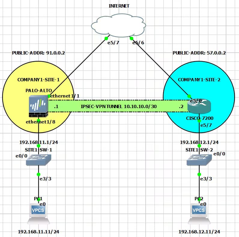
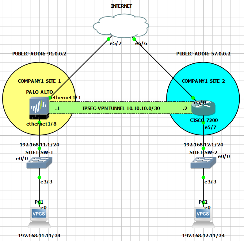
Below is our topology for this tutorial.
Initial Task: Setup the Palo Alto Next-Generation Firewall
An optional task for our other readers who are new to the firewall. The tutorial can be accessed here. It contains quick steps to make the firewall's Web-GUI reachable through the network.
Main Tasks:
Setup Site-to-Site IPSec VPN Tunnel
Routing Inside Tunnel Interfaces
Cisco Configuration
Palo Alto Configuration
Advertise Local Area Network (LAN) Subnetworks
Cisco Configuration
Palo Alto Configuration
Verification
Task 1: Setup Site-to-Site IPSec VPN Tunnel
In this task, we are going to configure a Site-to-Site IPSec VPN tunnel between our Cisco Router and Palo Alto Next-Generation Firewall. I created a dedicated article which is a step-by-step tutorial. You should study it here.
Task 2: Routing Inside Tunnel Interfaces
1. Cisco Configuration
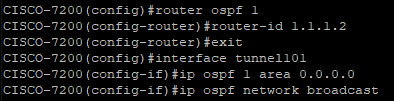
We configured an Open Shortest Path First (OSPF) and applied it to our Tunnel interface. Router ID is optional in Cisco as it has its own way to automatically add an OSPF Router ID. Make sure to configure the OSPF network-type as Broadcast as we are matching Palo Alto's default setting.
2. Palo Alto Configuration
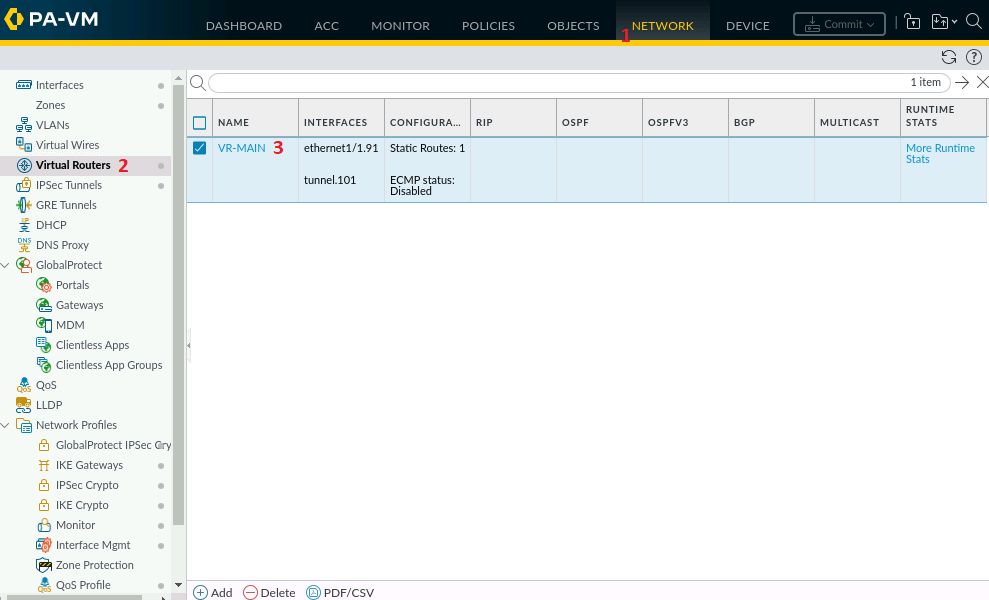
In NETWORK > Virtual Routers, click the name of our virtual router, in our case, "VR-MAIN."
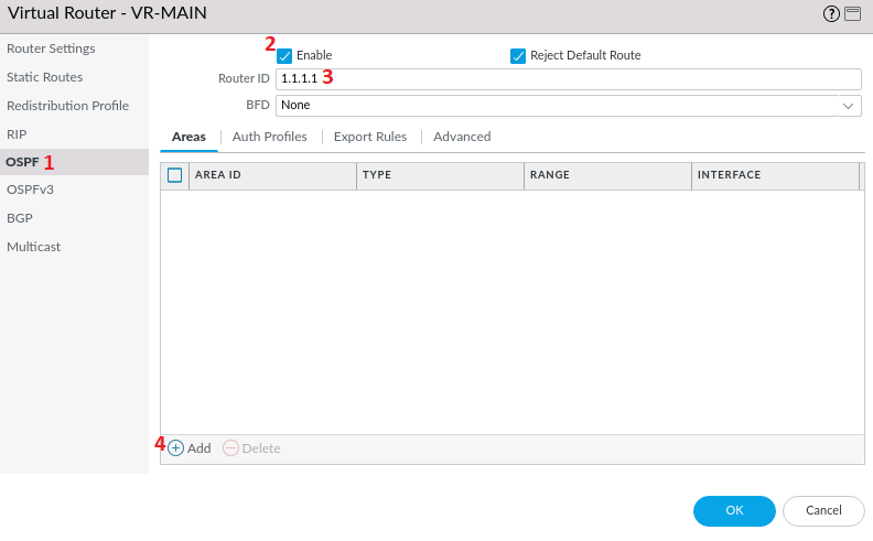
In the pop-up window, select OSPF and check Enable. Router ID here in Palo Alto is required, in our configuration we put 1.1.1.1, then click Add.
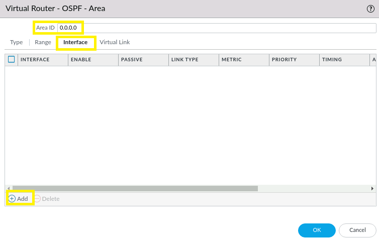
Leave the Type as Normal. Set the OSPF area to 0.0.0.0 which is the same as Tunnel101 in our Cisco Router.
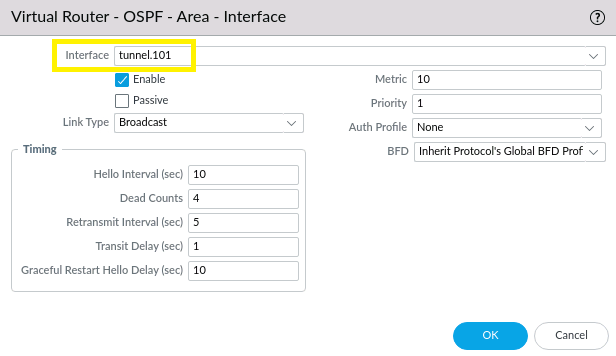
Apply our tunnel interface created in Task 1. Leave other fields untouched, and click OK. Commit changes.
IMPORTANT!
OSPF neighborship might not establish with an EXSTART state and below alert.
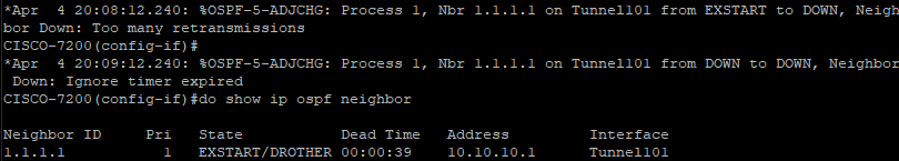
The issue is simple: MTU size is the culprit!
To fix, we need to set the same MTUs in our tunnel interfaces.

Above we checked Tunnel101 MTU size (1427 bytes) in our Cisco router. Our next action is to configure the same in our firewall.
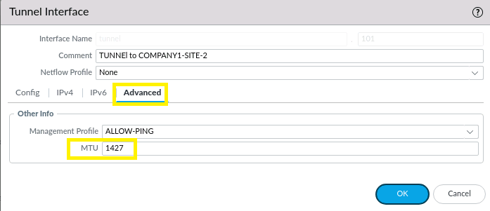
NETWORK > Interfaces > Tunnel > tunnel.101 > Advanced tab has a field to set the Tunnel interface' MTU size. Click OK and Commit changes.
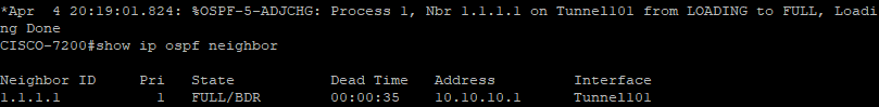
You can now see that OSPF neighborship is established and in FULL state.
Task 3: Advertise Local Area Network (LAN) Subnetworks
1. Cisco Configuration

We enabled OSPF in the LAN interface.
2. Palo Alto Configuration
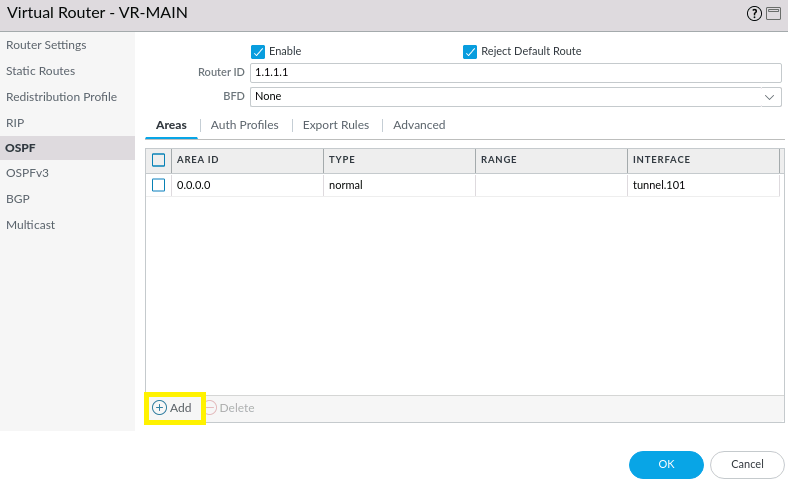
In NETWORK > Virtual Routers > OSPF, click Add.
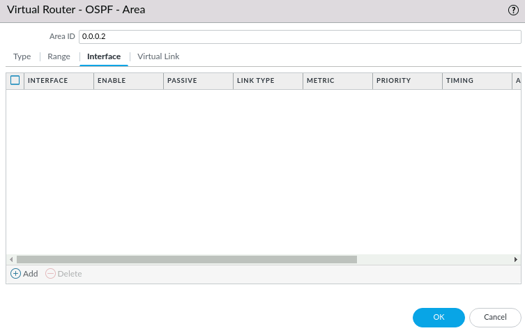
Our OSPF area to be used for this branch's LAN is 0.0.0.2, click the Add button below.
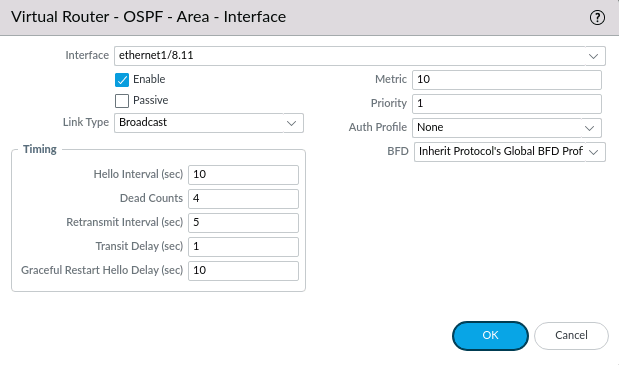
Select the interface ethernet1/8.11 and leave other settings untouched. Click OK and Commit changes.
Task 4: Verification
1. Cisco Verification
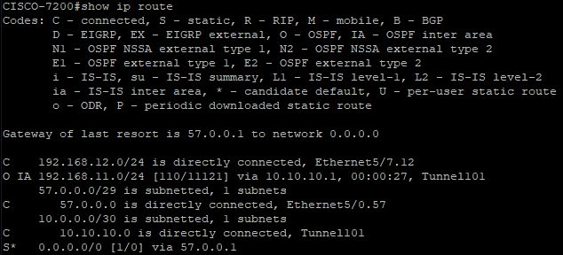
We can see in the show ip route command that the subnetwork from BRANCH1 is received by our Cisco Router through OSPF routing protocol and is reachable via our Tunnel interface, Tunnel101.
2. Palo Alto Verification
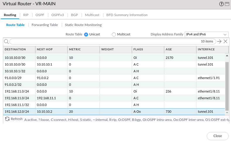
NETWORK > Virtual Routers > VR-MAIN's More Runtime Stats shows that the LAN subnet from our Cisco Router is reachable via our Tunnel interface tunnel.101
3. Ping Test
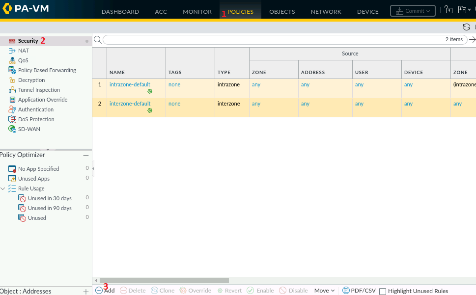
In Palo Alto Next-Generation Firewall, Security Policies protects network through the use of a Zone-based schema. Our current setup needs Branch-to-Branch LAN access. Currently, the LAN subnetwork 192.168.11.0/24 is in TRUST-ZONE-1 zone, and it needs to access VPN-1 zone where LAN subnetwork 192.168.12.0/24 resides. We will need a policy that enables traffic to pass from 192.168.11.0/24 to 192.168.12.0/24 and vice versa.
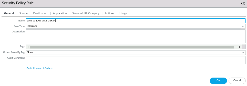
Rule Type interzone means passing traffic from one zone to another.
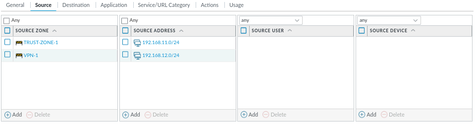
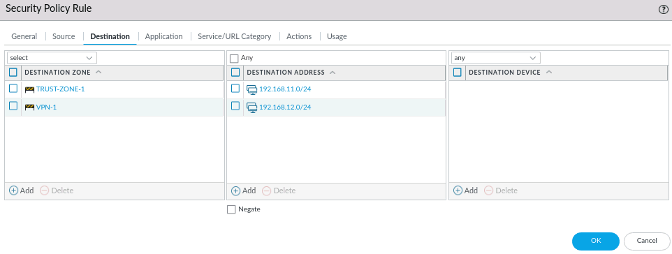
Use the same setting for Source and Destination tab. Leave Application as Any and Actions to Allow. Click OK and Commit changes.
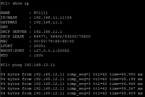
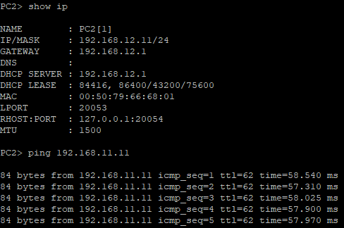
We can see now that Branch-to-Branch LAN can pass traffic between. PC1 (Palo Alto branch) and PC2 (Cisco branch) can now ping each other.
Conclusion
In today's article, we successfully connect our branches in different sites. During the process we observed that Palo Alto Next-Generation Firewall has some additional steps to co-work with our Cisco Router, such as creating a policy and matching the remote tunnel MTU size. Finally, the ping test tells that traffic is passing inside the tunnel. We can say that we are in the right track configuring our devices.
Any questions or suggestions? Comment it and I would be very happy to discuss that!